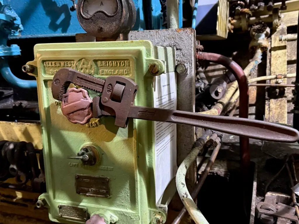
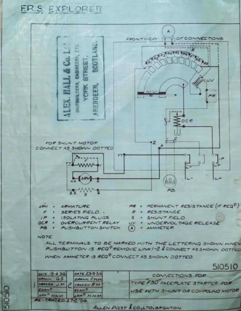
The Explorer has an air compressor the sole task of which is to supply compressed air to start the diesel generator. Being a fairly large DC motor there is a starter. specifically an “Allen West Type “FSO” faceplate starter for use with shunt or compound motor.”
The purpose of the starter is to limit the high starting current that would otherwise flow when a DC motor is first energised which would cause a big bang. It does this by inserting resistance in series with the armature.
The operator rotates a handle on the front of the starter, which moves a conductor across a semicircle of contacts (top right of the drawing). Each contact progressively cuts out part of the starting resistance, allowing the armature current to increase gradually as the motor accelerates and back-EMF builds.
There is a low voltage coil (LV) coil which holds the handle in the on position when the motor is running. This is an electro magnet. It serves as a safety device to ensure if voltage is lost the starter rotates to the off position. At some undetermined time in the past this coil failed.
In the interim, a Stilson wrench was used to hold the starter on as shown at the top of the page. Whilst this elegant solution is not ideal, given that this is essentially the only DC motor still in use there was little chance of an incident However, it was decided that a repair was in order.
The Explorer’s highly skilled team of rocket scientists (Duncan and Colin) went to work
The damaged coil was removed, but sections of the insulation were too degraded to reuse. Duncan therefore machined replacement insulation components on the formerly Royal lathe. The refurbished coil was then sent to Claremont Electric Motor Repairs for rewinding.
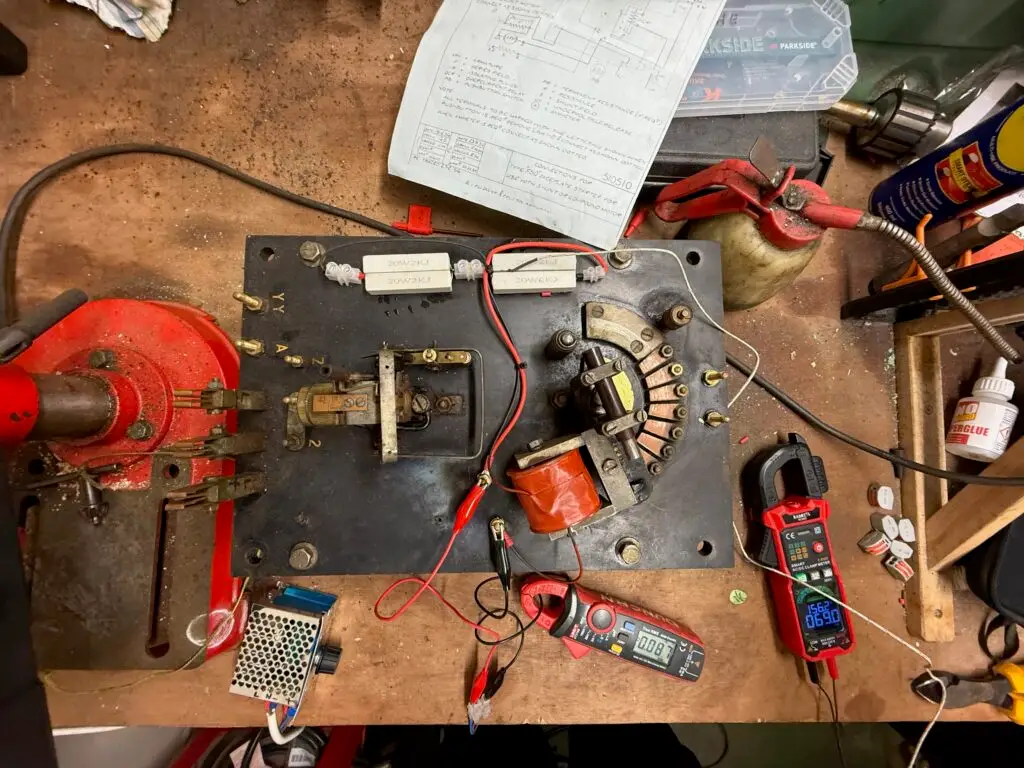
After rewinding, the coil was reinstalled and testing was carried out at the Jet Propulsion Laboratory pictured above. Initial tests showed the coil temperature rising rapidly, approaching 100 °C before I chickened out
Series resistors were introduced to limit the current, but this merely shifted the overheating to the resistors themselves.
The final solution was to divide the current between two parallel resistor banks. This arrangement, shown in the photo above, spreads the heat dissipation more effectively. The multimeter on the right shows a stable temperature of 69 °C, which was considered acceptable.
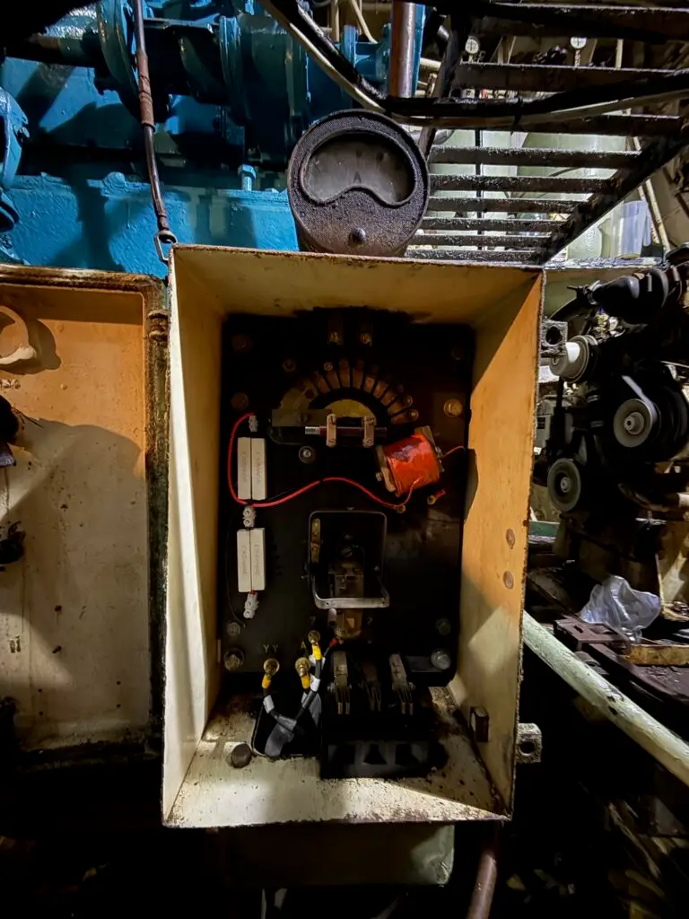
The bits were reinstalled in the starter box.
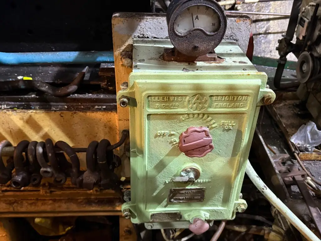
And voila (said Zebedee in French). Pictured above the starter with amps going to the running motor and not a stilson in sight. Well hardly any stilsons in sight, and certainly none serving as a UV coil.